Welcome to new 160m band blog

This blog is the replacement of the my preview Topband blog here http://topband.blog.cz/ because of an agressive advertising and flash banners inserted by the blog provider. For older posts access You can visit the old blog link which will exist still... but it will not be updated anymore.

Effective from 1st Jan 2017 please paper QSL via OM-bureau only.


Showing posts with label Antennas. Show all posts

Friday, April 24, 2020

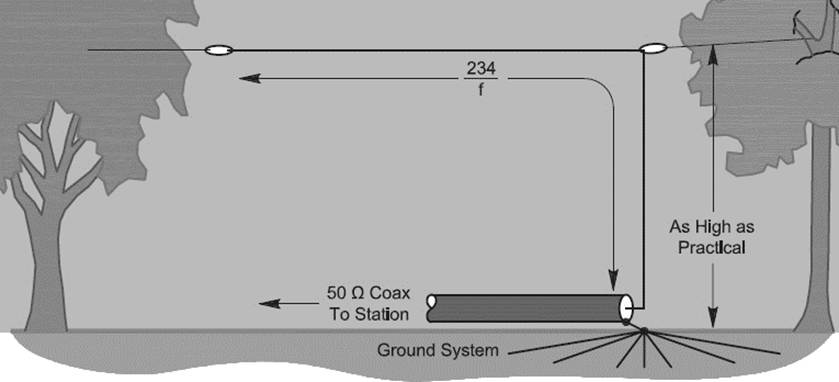
Capacitive loaded vertical?

Hi all,

did you tried this antenna in your QTH...?


73 - Petr, OK1RP
.../-.-

Thursday, June 27, 2019

Construction and design video-Beverage matching and termination by Steve, VE6WZ

Hi all,

An excellent "How to do" tutorial for low bands receiving Beverages antennas by Steve, VE6WZ can be found now on Youtube...

"A few weeks ago I uploaded a video on some 
design and construction ideas for Beverage 
matching and termination boxes. I show how to wind your own 
transformers, and present a few different enclosure methods.  
I show how I have designed and built some commercially made double 
sided boards for broadside phase boxes and 4 Beverage switch boxes 
using KiCad and OSH park.

https://youtu.be/r85MqK_N3a8 

This video is part of my "RX antenna series” which includes various 
videos about low-band rx antennas.  It is still a work in progress and 
in a week or so I will add another video about installing Beverage 
wires in the field, and a video about beverage maintenance.

https://www.youtube.com/playlist?list=PLipJSm0KKo3BgY8F6NQ1DH3070C3SaUMN 
 
73, de steve ve6wz" 
 
(Published on: http://www.contesting.com/_topband - Topband Reflector)
 

Pondering other 160m transmit antenna by Rudy, N6LF

Pondering other 160m transmit antenna

I have tested several vertical antennas, feed against buried radials 0.1 lambda long. The wire vertical component or stacked pipes or even the real tower on the hill...

I have tested also very tall (>100 ft) tree at the edge of my property vertical with moderate results on Top Band. I’m thinking of using the tree to support the vertical component, and going to an elevated radial system.


Also the grounded half loop with 30/20m vertical sections and 80m phasing elements i tested for several years including the 16x 0.1 lambda long radials laying on the ground.

This is an interesting read about elevated radials:

https://rudys.typepad.com/files/elevated-ground-systems-article-final-version.pdf

(Thanks to Rudy, N6LF for that article...)


73 - Petr, OK1RP
.../-.-

Tuesday, December 18, 2018

160m horizontal loop? ...why not!

Hi all,

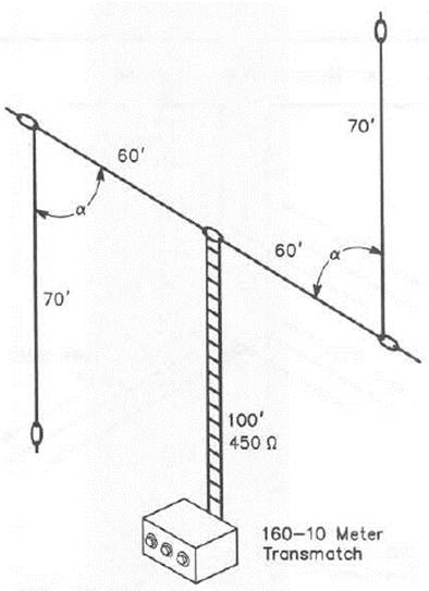
This 10 - 160 meter tuned horizontal loop antenna is fed with 450 ohm ladder line all the way into the ham shack to an Palstar AT1500BAL balanced line antenna tuner.


The above graphic depicts the overall layout of the loop antenna consisting of 558 ft. of #16 "silky" stranded wire cut to one wavelength long on the lowest operating frequency (160 meters). The mean height of the loop above ground is about 55 ft. The loop is suspended from from four corners by nylon halyard strong over the top of 4 adjacent trees as shown above.

http://www.designerweb.net/downloads/160m_Loop_Antenna.pdf


73 - Petr, OK1RP
.../-.-

Shortened antenna for 160m by ES4BD


Hi all,

if you are looking for antenna for TB but you have no more space than for 80m antenna then try to check antenna by ES4BD. 


http://es4bd.qrz.ru/part1/an160.shtml


73 - Petr, OK1RP
.../-.-

Wednesday, November 29, 2017

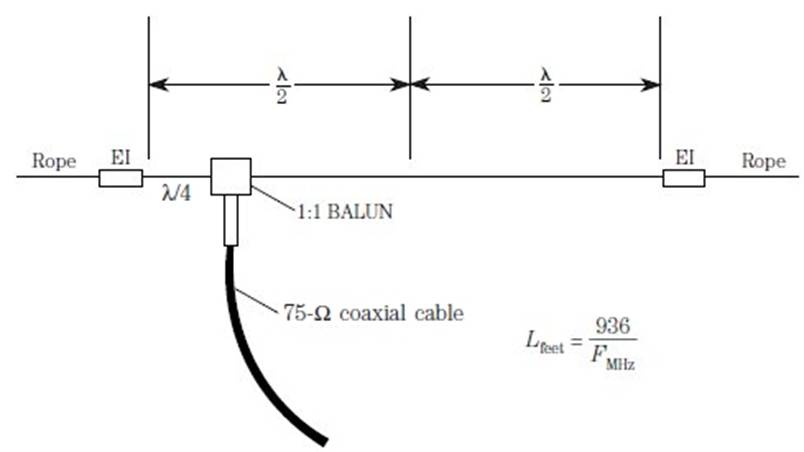
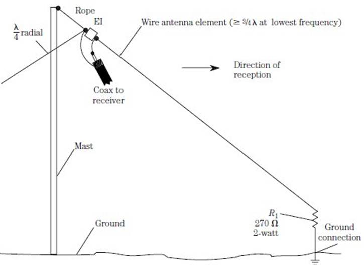
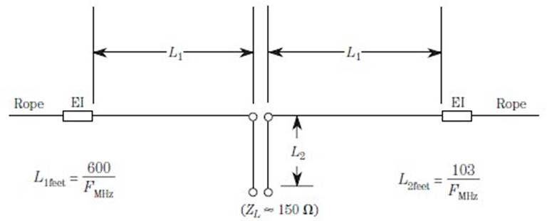
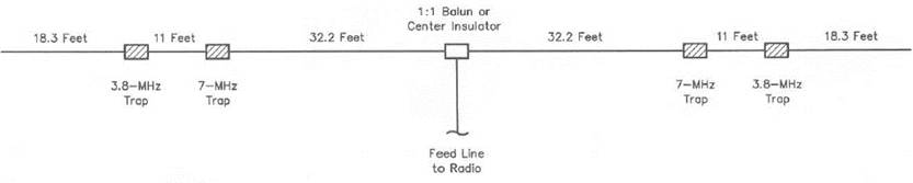
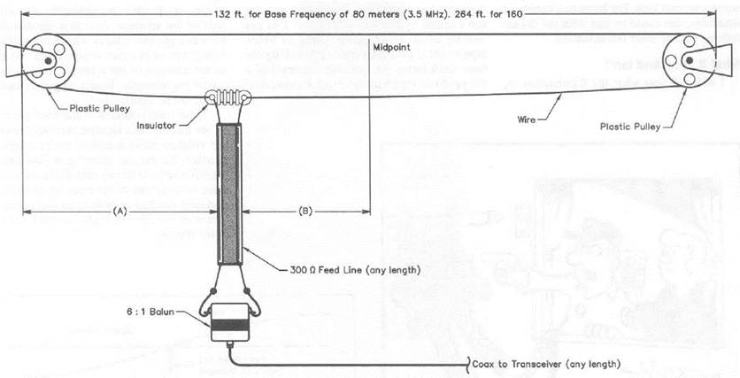
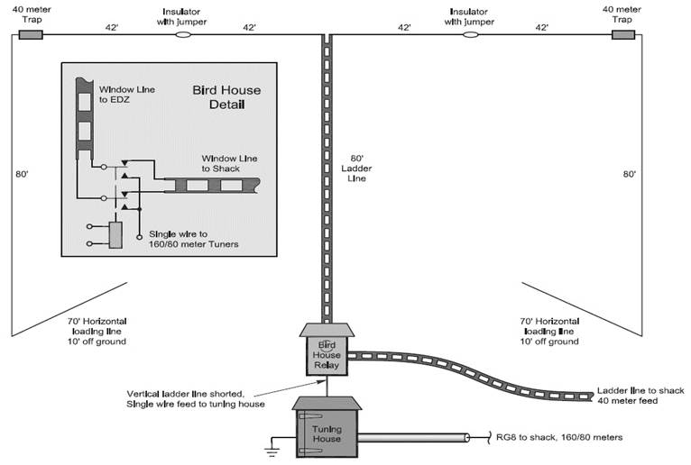
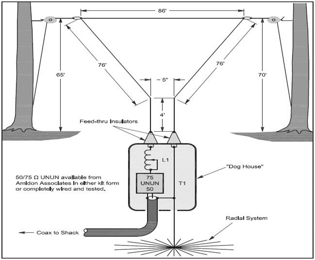
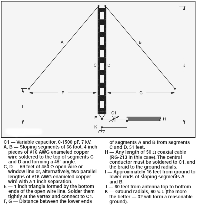
22 Different Wire Antennas for 160m compilation by TopbandHams


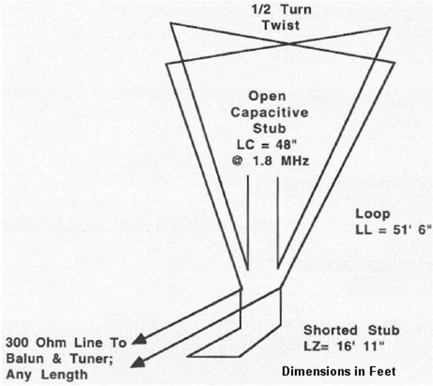
22 Different Wire Antennas
for the 160 Meter Band

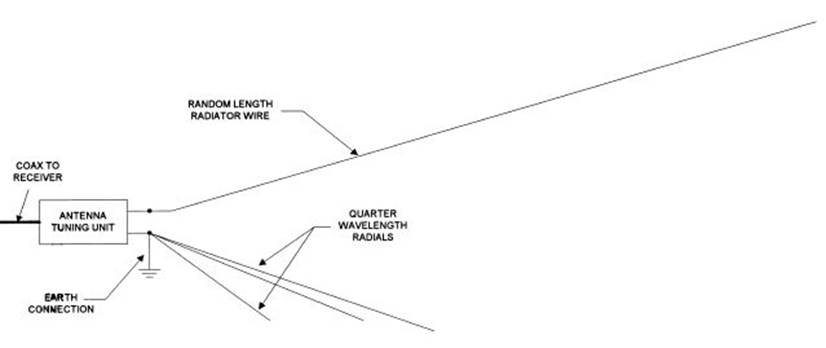
Random Length Radiator Wire Antenna


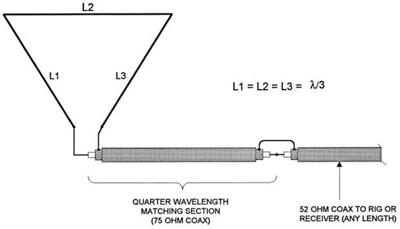
Delta Loop Antenna


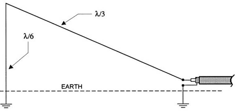
Half Delta Loop Antenna


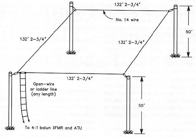
1.9 MHz Full-Wave Loop Antenna

Off-Center-Fed Full-Wave Doublet Antenna


Terminated Sloper Antenna

Double Extended Zepp Antenna


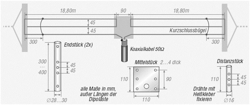
40m - 80m - 160m Short Dipole Antenna


10m -160m Multiband “Z” Antenna

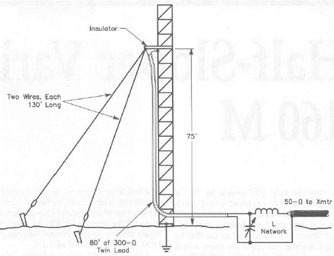
160m Half-Sloper Antenna

160m Linear Loaded Sloper Antenna

Super-Sloper Antenna


Clothesline Antenna


160m, 80m, 40m Curtain Zepp Antenna

160m Inverted Delta Loop

160m Capacitance Loaded Vertical Antenna

160m Inverted-L


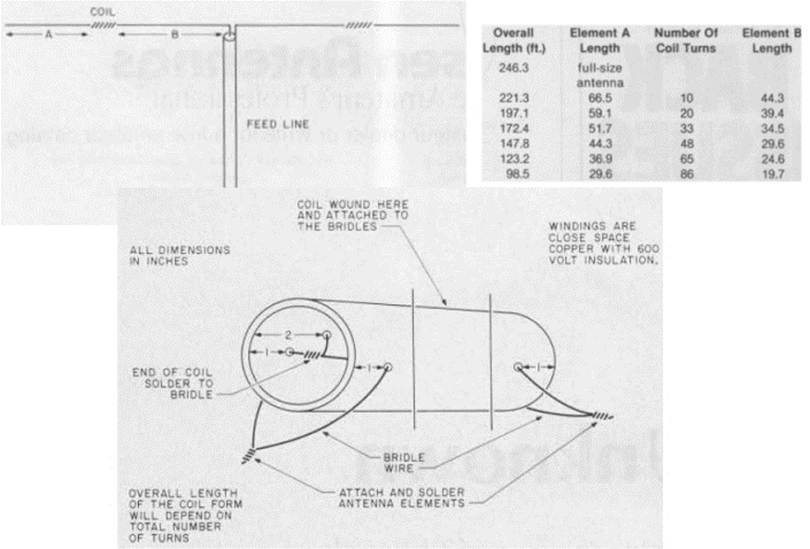
160m Inductance-Loaded Shortened Dipole

160m Loop Antenna for TX


160m and 80m Morgain-Dipole Antenna


160m Twisted Loop Antenna

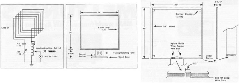
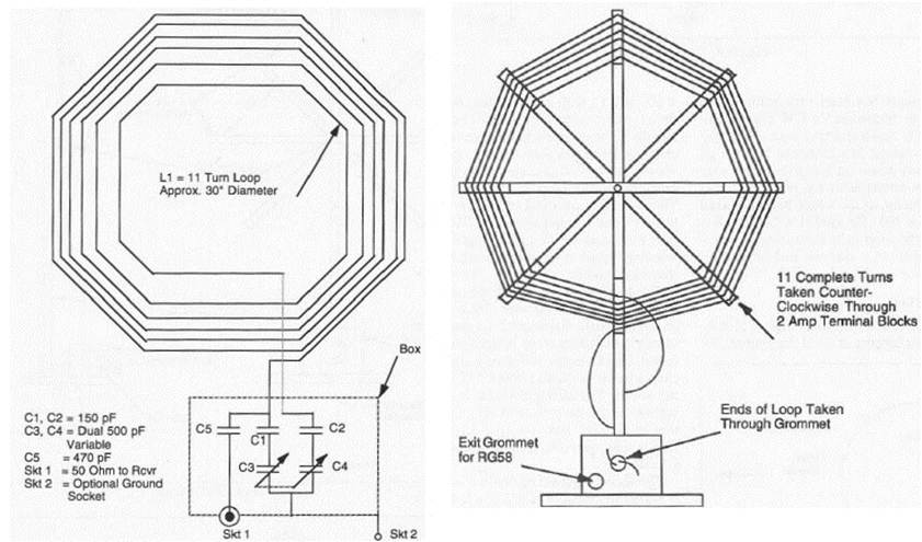
160m DX RX Loop Antenna


References:
Antenna Toolkit - J. Carr
Practical Antenna Handbook - J. Carr
More Antenna Classics - C. Hutchinson
Amateur Radio Techniques - P. Hawker
ARRL Antenna Handbook 1990-2007
ARRL Handbook 1990-2009
ARRL Antenna Compendium
73 Magazine 1970-2002
Funkamateur Magazine 1990-2011
RSGB Handbook - 2007 - 2010


Tuesday, January 24, 2017

The half sloper antenna - everything depends to your installation...


Proper installation by Jens, OZ1LWT
Hello,

I noticed that several people is complaining about the half sloper antennas performance and the results are completely different from different users.

I have the sloper for several years. I tested several versions including the big loading coil at the feed point (avoid it) as same as trapped slopers and many others. There are some things that you should know about using any half sloper including the commercial ones.

1. Regardless of what manufacturers claims any half sloper is most effective when it is mounted on a tower/mast at the 30 - 60 foot level (35ft works well for me) and the tower or mast has a large tribander or VHF antennas (at least) on it. This gives the system some top loading.


The antenna grounding under test without the radials

 2. Mounting it on a pole with a lead to ground is not going to get it done and it is definitely not enough to get good performance. I have tried this on occasion and the performance is degraded considerably. Same as mounting it on a tree or on the side of a house even although I will install the grounding wire down to the radial system. You will be able to make contacts, but a low dipole or loop will almost always make similar job or even will out perform a half sloper set up this way.

3. These antennas are primarily vertical radiators and do a decent job on DX at 40/80/160 meters in case of proper installation.


Good grounding is needed (another pipe goes up for beam installation

 4. In any kind of shortened slopers (to get total length of about 15-20m) using big coils the SWR points are about 10-15kHz either side of resonance because it is shortend for that band a lot. My full quarter wave 160 half sloper during short test had about 60% more bandwidth then these shortened ones.

5. The addition of a radial set tied to the tower/mast seems to make a positive difference. I did some testing over the air using 16pcs of 1/16 wl radials and without and most stations report that there was more punch to the signal when using a radial system although it did not always show up on the S-meter. Performance without a radial system is usable however.


Sloper under test without the beams top loading setup

 If these antennas are set up correctly either the commercial ones or a simple quarter wave wire set up as a half sloper will work fine.


If you will not set up it properly, you will be very dissapointed...


73 - Petr, OK1RP

Tuesday, December 10, 2013

The receiving small loops comparison by Rick, N6RK

Hello,

Rick, N6RK posted on Topband reflector very interesting article about his small receiving loops comparison. With his kind permission I am posting it over here as I am sure that it can help to each others and it can be good starting point for own tests in our QTH's.

Here is post from Rick, N6RK:

For the second night of the ARRL contest, I set up
three receiving loops with a switch to compare them in real
time. A Pixel circular loop (10 foot perimeter) using the
30 dB Clifton Labs preamp that comes with it was the first
antenna. The second one was a square 20 foot perimeter
shielded loop as I described in the Sept./Oct. 2009 National
Contest Journal:

http://www.n6rk.com/loopantennas/NCJ_loop_antenna_N6RK.pdf

The third antenna was a square 40 foot version of the loop
in the NCJ article. No external preamp was used with the 20
and 40 foot loops. The receiver was a Yaesu FT-1000 with its
internal preamp turned on. All three loops were oriented
to null at 30 degrees azimuth on ground wave, which
minimizes the noise at this QTH.

After comparisons on dozens of stations in the contest,
the clear winner was the 40 foot loop. In general,
the noise levels of the Pixel and the 40 foot loop
were similar. However, the latter had 6 to 10 dB
more signal, resulting in a markedly improved S/N ratio.
There were numerous stations where a signal that was Q5
on the 40 foot loop was inaudible on the Pixel.

I ended up just leaving the switch on the 40 foot loop
for the balance of the contest. If I had to have only
one loop to use, it would be an easy decision to go with
the 40 foot one.

The 20 foot loop had signal levels comparable
to the Pixel, but the noise level was considerably lower.
It came in 2nd place. The signal level of the 20 foot
loop has always been marginal for the FT-1000 without
external preamp. It might help to have some preamplification
on it. I would rather use a larger loop than fool with
a preamp. We have strong BCB signals, including one at
1,700 kHz, so preamps are always problematical.

The 40 foot loop will work (on 160 meters only) with an
unmodified antenna circuit board, however, I ran into
BCB QRM of the tuning diodes. I removed one of the two
tuning diodes, which allowed the tuning voltage to rise.
This helped on the BCB QRM, but there was still some lite
hash heard. Finally, I went to four diodes in a series
parallel configuration as described in the article. This
fixed the BCB QRM. The final configuration tunes from
about 1.25 to 2.5 MHz, covering WWV.

I also compared to the transmit vertical. In most cases,
stations could be copied on the vertical, but maybe not
at 100%, and even when they could be copied, there was
the usual unpleasant impulsive noise, as compared to the
gentle rushing noise of the loops. From a listening
fatigue aspect, it is not good to have to listen on the
vertical. I have no technical theory to explain why
this is, I just observe it consistently.

The Pixel loop covers all the way to 30 MHz. It still
may be a useful receive antenna on the higher bands.
When I purchased it for evaluation, I suspected that
160 meters was not its strong suit. Below 160 meters
on BCB, the signals are much stronger and the Pixel should
have no problem. Thus the take away is only that
the Pixel isn't very useful on 160 meters.

The mechanical construction of the 40 foot version is
much more difficult that the 20 foot version. My initial
attempt was successful enough for these tests, but was
basically a discovery of what NOT to do. It did become
clear that it is much easier to guy the vertical support
rather than making it self supporting. I am interested
in hearing about successful large loop construction
techniques.

Rick, N6RK

As I have the coaxial loops in two versions > K9FD and N6RK design and finally I arranged also the Mini Diamond wire loop designed by Pete, W2PM I am interesting a lot in the results of comparisons on my really small "post stamp" lot.
So I am going to try to make similar tests and we will see the differences.

73 - Petr, OK1RP
.../-.-

Friday, November 29, 2013

Base loaded half sloper - part I.

Hello all Topbanders,

it's really long time ago when I posted the last article. I would like to send my appologize to all of You. I hope that I will be able to update this place more often...

In preview articles "Antennas inspiration"we talked about different antennas suitable for small pocket size lots. In fact I am still looking for some of that also as my fixed QTH is so small that I have no more than 10m x 15m garden available and just 6m high roof. No tower, no trees around.

Some time ago I found interesting article about shortened half sloper writen by Don, WD8DSB. There is what I found as the first on the internet about this type of the antenna:

Rugged 160 Meter sloper...

Our best selling antenna is our 160 meter, ruggedized version of our popular "half-sloper". We have been building these antennas for over 12 years. They work and work well.
It's features heavier, 14 awg insulated wire, a built-in SO239 connector and a solid cover over the coil. Ideal for 100-150 watt radios, this antenna solves the problems of working "top-band" and eliminates the need for a tuner. Trimmed to resonance at your favorite spot in the band this antenna offers omni-directional performance with minimum effort.

We start with a tightly wound 14 awg insulated wire coil.


This is the finished antenna, ready to be hung on your tower.
The radiator wire will be left several feet long to allow you to "prune" it to the length that tunes it to the exact spot in the band that you need. Once tuned near the center of the band at your location the antenna will cover the entire band without any retuning or tinkering. Note: this antenna can withstand quite a bit of power but we have NOT tested it above 150 watts. We don't build "high-power" antennas. We build antennas that give you that extra performance.


This antenna ships 75' in length and will be trimmed back to 68' or less on installation. It works best when attached to your tower at about the 45-50' level. This allows the wire to be angled down to the ground at a comfortable angle (somewhere near 45 degrees) and attached to a suitable support 8 or 9 feet off the ground ( to keep someone from touching it while you are transmitting) 45' or so away from your tower.

We have had one of these on our tower for 12 years with no problems.


We have made several improvements to the design over the years. The one shown here is a very early production model. (12 years in use...)

73 de Stan, KC5UYF

OK, it sounds good. What is important is that the installation need to have grounding point and some pipes or way to simulate the vertical part of the half sloper going to ground or better to the radials system.

The minimal height seems to be around 8-10m. Of course not for DXing but to come to TB in general. I am going to thinking about that...and need to find the original post from Don, WD8DSB.

73 - Petr, OK1RP
.../-.-

The 160M "No Excuses" Homebrew Vertical by John, K6MM

Hello,

some months ago I attended on the web seminar about the 160m antenna for limited space. Excellent presentation done by K6MM was named "No Excuses" homebrew vertical. I found this design very interesting so I am preparing some hardware and I will try to work on it in the summer time because my post stamp lot is quite similar to the John's one.

When I discussed about this antenna on few hamfests then I have got several emails about the antenna construction and I was asked for contact to John, K6MM etc.

So there I am posting the link to John, K6MM page where You can find all informations regarding his nice project.

I will be glad to get feedback over here about the performance in Your location.

73 - Petr, OK1RP
.../-.-

Inverted L for restricted space...

Hello,

when I looked for more information about my antenna (base coil loaded half sloper) I found interesting antenna also for restricted space.


In fact the vertical part is helical vertical where 11.7m of insulated 2.5mmsq wire is wounded on the 5m of the fiber glass pole including the wire going to point A for feed line. The spacing for the winding is approx. 1.5cm.

The 2x 18.1m of the insulated wire used for radials on the ground is compromised solution for that installation. Definitely it's needed better grounding system and 16x 16m is recommended as minimum where 3dB loss is expected.

Well I did not tested it but for those who are space limited it can be inspiration for experiments.

Do not hesitate to share with us Your experiences with compromised antennas like this.

73 - Petr, OK1RP
.../-.-

ZJ Beverages and how it works - part II.

Hello,

as I promised there I am posting the open discussion about the ZJ Beverages as I found it on the reflector.

TopBand: ZJ Beverage Box Comments and Update de W0AH
from [W0AH@aol.com] [Permanent Link][Original]
To: <topband@contesting.com>
Subject: TopBand: ZJ Beverage Box Comments and Update de W0AH
From: W0AH@aol.com (W0AH@aol.com)
Date: Wed, 5 Nov 1997 16:47:09 -0500 (EST)

On Oct. 22 I posted to the list that I was not happy about the performance of my NE beverage and also that my ZJ Beverage Box was not working and that I was going to try and fix it.


Several wrote and asked me to send them any information I received since
they also need ed to fix the ZJ beverage box. Therefore, this post.
First, I want to say that my ZJ beverage box worked fine when I first
installed it a couple of years ago. It brought my beverage signal up 2 or 3S-units as I recall. I had no intermod (I have no local commercial
stations). Using a coaxial hand switch between the transmitting antenna and the beverage (my transceiver had no separate receive antenna), I forgot to switch the antennas and ran power into the ZJ box.


I wrote ZJ, which a month later sent me a replacement device, gratis.
Now, over a year later, wanting too repair the ZJ box, I can not find the device he sent me. Thus my inquiry to the list recently.


My ZJ Box did not come with a schematic which is my main complaint.
Looking at the device, I thought it was a gasfet, but I have been informed by KM1H, W8JI, and K0CS that it is a MMIC. MMIC stands for Monolithic Microwave Integrated Circuit Amplifier. I have built several of the well regarded Down East Microwave kits (for 902, 1296, and 2304 MHz) which use MMICs. Both KM1H and W8JI wrote that the MMIC was a poor choice for a 1.8 MHz preamp. I agree that it is an odd choice, but my Avantek Semiconductor Data Book shows that the power gain and other MMIC specs are flat from about 0.1 to about 1 or 2 GHz, depending on the specific device. Also, the Avantek power gain versus frequency chart shows them being flat to DC! Therefore, the device should be suitable for 1.8 Mhz.


KM1H siad there had been a discussion of the ZJ Beverage Box which can
be found in the archives. So more information is available there. He also said that the ZJ Boxes had been shipped with "at least 4 different" MMICS including the MAR1, MAR3, and others. He stated that some of those devices needed different biasing. He also stated the ZJ Box was subject to overload and IMD. Carl said the "ultraminature 9:1 balun is just as bad." W8JI suggested replacing the MMIC with "a regular CATV transistor."


W4MPY wrote that his ZJ beverage box filled up with water and that he
has tried unsuccessfully to get help from ZJ.


Both W8JI and KM1H stated that a good beverage will not generally need
a preamplifier.


K0CS kindly sent me a MAR-3 device which had been supplied by ZJ as a
replacement device.


Looking at the various Avantek MMIC specs (I can not find my cross
reference to compare the Avantek MSA MMICs to the MAR MMICS) I see several MMICs with very similar specs (in some cases just different plastic packages-ie. cases). Almost all of them require 4.5 to 5.5 volts DC. I suspect the several different MMICs supplied in the ZJ boxes have identical specs at 1.8 MHz and that biasing is not an issue. For those who need to replace the MMIC, a MAR-1, MAR-3 or equivalent should work fine. MMICs are listed in several of my electronic catalogs for about a dollar each.


I hope the above is useful information and that some of you get your ZJ
beverage boxes back up and running. Unfortuately, mine still is not working after I replaced the MMIC. I suspect that the ultraminature balun, as KM1H described it, needs replacement. Not sure I want to proceed until I get a schematic. Does anyonwe have one? See also my next post on beverage transformers. Doug W0AH


TopBand: ZJ Beverage Box MAR3 MMIC Replacement?
from [km1h @ juno.com] [Permanent Link][Original]
To: <topband@contesting.com>
Subject: TopBand: ZJ Beverage Box MAR3 MMIC Replacement?
From: km1h@juno.com (km1h @ juno.com)
Date: Thu, 23 Oct 1997 18:58:41 EDT

On Thu, 23 Oct 1997 15:44:36 EDT W0AH <W0AH@aol.com> writes:
>Thanks K0CS for the info that the ZJ Beverage Box uses a MAR3 MMIC,
>which are quite inexpensive .

Wrong info Doug. Your ZJ "thing" has a MAR-1 in it according to ur
number. Owners have found at least 4 different MAR MMIC's so far. NOT interchangeable without changing bias resistor either.

As discussed here at length a month or so ago, the choice of device PLUS
the matching xfmr in the ZJ box makes it an all around poor choice for Beverages. Nice and cute toy but no good for real world use. Suggest you check the Archives for comments by users, W8JI, myself, etc.

73 Carl KM1H


I thought I had a MAR3 around here, but can't find it.
Can any of the following Avantek be substituted for the MAR3?
Avantek 0185, 0285, 0485, 0685?????
I'll post a message as to how this all turns out as others have contacted me concerning their non-working ZJ Beverage boxes.
I have the above. If no answer, I'll try to call WB5LUA, Mr. MMIC!
Doug W0AH

Well any other experiences with this system even negative are welcomed over there.

73 - Petr, OK1RP
.../-.-

ZJ Beverages and how it works - part I.

Hello,

when I discussed some time ago about the Beverages and neccessary boxes I mentioned that one of my Beverage sets is W2ZJ system. After several emails received from some of You I decided to scan the user guide as it is not available on the internet.

I have not enough time to replying to each of You for questions about ZJ Beverage boxes...how it is designed and which parameters it has.

So there are all information I have and let's go to check it guys.


I am planing to install the ZJ boxes and test it as I heard a lot of negative reviews about it. On the other hands it's promissing the system with pre-amp on the Beverage side then sigs going to shack enough strong and filtered.

As I need the strong negotiation with neighbours to install the 164m of insulated wire on the 2m stands in country side I am not sure when I will be ready to test it.

Does anybody used ZJ Beverages and how it worked for You please?

73 - Petr, OK1RP
.../-.-

W2PM MiniDiamond RX loop by OK1RP - part I.

Hello,

as I am still looking for the receiving antenna which will allow me to improve the receiving performance on my pocket size QTH (250msq) I was very happy to get construction details and description of receiving loop with name MiniDiamond from Pete, W2PM. I have to say that Pete is real gentleman and he provided a lot of effort to help me with RX antennas. Pete helped me to understand how to build the very small loops effectively for 160m band.

So after some time I decided to start with building the MiniDiamond loop and as Pete said I am making it as large as possible. All will be posted here step by step according to the progress of building. You will see used hardware, construction, mounting process, measurement and testing of the final product as same as the on-air results. If the antenna will not work then You will be able to check where I made the fault and learn from it to avoid Your own issues.

Today I will show You few pictures from bulding the main cross support.


I decided to use bamboo as the main cross support because all the other materials seemed to me worse. Fiber glass poles are too breakable, plastic poles used quite often as potatoes support on the garden are too heavy and short as same as wooden poles. On the picture You can see the used tickness. The only problem was in the local store with finding few bamboo poles enough straight, hi.


As the mounting support I used universal plate from the local store. You can see a lot of holes in the plate...great as I did not need to make any hole just decide for right one with the screws.


The cross support is already done waiting for mounting the last wooden part which will be screwed on the rotor unit. I hope that it will fit to the old rotor used for light UHF antennas...


Finally You can see the box arrived by snail mail with non-inductive resistor and 900/50ohms transformer units all in nice water resistant plastic houses.


If You are interesting in this RX Loop kit then be noted that they are available for loops, Beverages and also Ewe antennas in different versions like BNC, F connectors etc.

That is all for now and see You soon with some progress with building the loop.

73 - Petr, OK1RP
.../-.-


Friday, November 15, 2013

MW stick vs. Half Sloper antenna receiving test by Petr, OK1RP - part I.

Hello,


when I spoke to several DXers about the Mini Whip stick all of them said "uhh, Petr if You are interesting in serious operation on TB then forget it and focus on good RX loops or so".

I do not like to evaluate or reprobate anything (specially antennas) without testing it first and mainly You never know which antenna and when will help you to hear weak signals on the TB so...I have this stick now and there is comparison with TX antenna > based coil loaded 11m high half sloper (see preview article about it)...

10/11/2010
22:45 160m W1MK S6/sloper S5/MW (better s/n on MW)
22:53 160m N3IR S3/sloper S2/MW (better s/n on MW)
23:20 160m VE1ZZ S5/sloper S4/MW (the same readability)
23:20 160m 9K2YM S6/sloper S5/MW (the same readability)
23:30 160m W8FJ S5/sloper S5/MW (better s/n on MW)
23:33 160m K1VW S4/sloper S4/MW (better s/n on MW)
23:35 160m TK5IH S6/sloper S5/MW (similar readability)

My personal feeling > in most cases the signal levels from MW were lower but quieter. The s/n ratio was definitely better on MW although the differences was not big sometime. Only in one case (TK5IH) I though that reception is better on Half Sloper because of stronger signal. 

The Mini Whip stick was mounted inside of the house in the attic just 50 cm bellow the ridge of the roof. Feed-line about 10m of the 50 Ohms cable down to the radio-room. Half Sloper is mounted about 5m far from the MW using the pipes into the total height of 11m where the base coil and sloped wire is mounted. Feed-line is 27m of cable going down to radio-room. No radials yet just copper strap going along the pipes down to ground where it's connected to grounding point.
The distance between both antennas is no more then 5m.

Used radio Elecraft K3 where Notch 900 Hz masking used, AGC off, AF gain at 11 o'clock, RF gain at 12:30 o'clock, DSP BW 150 Hz (200 Hz IF Inrad).

Of course there is no doubt that this stick is not comparable to full size Beverages or full size RX loops like Delta, K9AY or even Hi-Z phased verticals array but be noted that we are looking for "makeshift" solution compare to noisy TX antennas !

Interesting results...isn't it? What do You think about it?

More information You can find here: PA0RDT or here G3GRO

73 - Petr, OK1RP
.../-.-

Sunday, January 20, 2013

ALA-1530 vs RF PRO-1 by Guy Atkins

Hello,

with permission from Guy Atkins I am posting over here very interesting comparison study of small receiving loops commercialy offered on the market.

Let's go to read what Guy wrote:

For the last few months I've been doing some methodical comparing of the signal-to-noise (S/N) ratio of many stations as heard through the Pixel Technologies RF PRO-1A and Wellbrook Communications ALA1530 active loop antennas. Using the spectrum analyzer qualities of the Perseus SDR receiver I've been able to be very objective on which loop antenna gives the best reception on all the LW, MW, and HF bands.

I've written a detailed review of the two loops which contains S/N charts for all bands, plus a selection of "A-B" comparison MP3 recordings and the original MS Excel spreadsheet file of raw S/N data available for download.

I've sent the review to some DX hobby web sites for possible publication, but Wellbrook has chosen to make the PDF file available now for download from their site:

http://www.wellbrook.uk.com/reviews/ALA1530-vs-RFPRO-1AReview.pdf

I hope you find the comparison review useful. It was very interesting and refreshing to use a receiver like Perseus as a S/N measuring tool rather than just making observations "by ear" as I've done for all my previous reviews and articles over the years.

Yes, you may certainly share my article on your blog. Besides the link to the PDF on Wellbrook's site, it is also found here:

and here
73,

Guy Atkins
Puyallup, WA USA

I hope that You will find it interesting and motivating...

73 - Petr, OK1RP
.../-.-